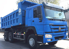
Many thanks for choosing HOWO trucks ! Pease read this manual carefully before the new vehicles run into operation. And hope you could enjoy your driving experience .
This manual is the latest editon for vehicle's operation and we reserve the rights of technical alteration and upgrades for better improvement without prior notice !
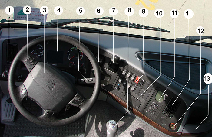
The general overview helps you to know instrument panels and control equipments.
|
Item |
Description |
|
Item |
Description |
|
1 |
Warm air outlet |
|
8 |
Transmission shift handle |
|
2 |
Horn button |
|
9 |
Button switch control panel |
|
3 |
Steering wheel |
|
10 |
Ashtray |
|
4 |
Combination instrument |
|
11 |
Air conditioner control panel and LCD |
|
5 |
Cruise control switch |
|
12 |
Cigar lighter |
|
6 |
Handle of hand brake valve |
|
13 |
Cup seat |
|
7 |
Handle of trailer hand brake valve |
|
|
|
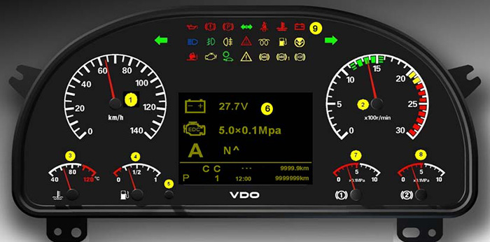
Combination Instrument CMIC
|
Item |
Description |
|
1 |
Speedometer |
|
2 |
Engine tachometer |
|
3 |
Engine water temperature gauge |
|
4 |
Fuel gauge |
|
5 |
Subsection mileage/Subsection mileage fuel consumption reset button |
|
6 |
Air pressure gauge of brake circuit 1 |
|
7 |
Air pressure gauge of brake circuit 2 |
|
8 |
LCD |
|
9 |
Alarm indicator |
Combination Instrument Function Instruction
1. Speedometer
The speedometer displays vehicle’s running speed.
The speed will be zero if error occurs in the communication between tachograph and CPU, meanwhile the error indicating massage will be displayed on the combination instrument screen.
The vehicle odometer and phase mileage information will be displayed on the lower right corner of screen.
2. Engine Tachometer
The engine tachometer displays engine rotating speed.
The needle will stay at the position which is +5° exceeding maximum when engine rotating speed is over scale range.
3. Engine Water Temperature Gauge
It displays the temperature of engine cooling water.
The alarm indicator of engine cooling water temperature will light up when temperature is over 95℃, meanwhile the serious alarm indicator flashes and buzzer gives an alarm.
4. Fuel Gauge
The fuel gauge displays fuel quantity in the fuel tank.
The fuel alarm indicator will light up when the fuel quantity is less than 1/8 of total fuel capacity in the fuel tank.
5. Subsection Mileage Fuel Consumption Reset Button
When vehicle is parking, press the button continuouslly more than 2 seconds, which is used to reset subsection mileage/subsection mileage fuel consumption.
6. LCD
It displays many kinds of information, such as accumulative total mileage, subsection mileage, time and so on. All the information is dispatched from CPU to combination instrument through data bus and displayed on LCD.
According to display sequence and detail functions on LCD, the displaying contents of each page is introduced as follows:
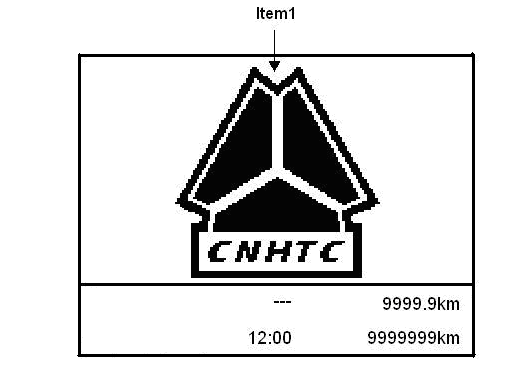
6.1. Logo
The logo “CNHTC” will be displayed within 1.5 second after key switch turns on. Please refer to picture.
6.2. Normal Driving Information
Display vehicle information under normal driving, refer to picture
The contents are displayed as follows:
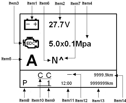
Electric Source Voltage (Item 1, Item 2 in Picture)
Display electric source voltage in the form of figure on LCD, range: 0–32 V.
Oil Pressure of Engine (Item 3, item 4 in Picture)
Display oil pressure in the form of figure on LCD as well.
Transmission Gears Information (Item 5 and item 6 in Picture)
When installed manual transmission, it shows N, R and blank on the Item 6 position which means neutral, reverse gear and forward gear.
Cruise Working Indicator (Item 10 in Picture)
When vehicle comes into cruise driving, it displays “CC”.
Time (Item 11 in Picture)
Time displaying: The time will show tachograph’s time if system connects with tachograph of VDO which connects chassis CPU through CAN bus.
If tachograph of VDO is not equipped, the displayed time will be set by the customer after system electrifying.
Accumulative Total Mileage of Vehicle (Item 13 in Picture)
Display range: 0~9999999km.
Subsection mileage (Item 14 in Picture)
Display range: 0~9999.9km.
If accumulative mileage exceeds displaying range or press subsection mileage/subsection mileage fuel consumption reset button for 2 seconds, subsection mileage and subsection mileage fuel consumption will be reset.
6.3. Displaying Page of Working Information
It is used for displaying some system working information of vehicle, such as working indication of differential lock, lifting axle, PTO and EVB, ect.
There are seven indication symbols displaying on the LCD, which is divided to display on two screens.
Displaying pages refer to picture 6.3 and picture 6.4:
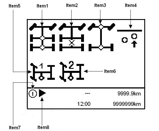
Indicators Description in Illustration:
Item 1:Working indicator of interwheel differential lock
When interwheel differential lock is at the right place, the indicator symbol hushes on the LCD; otherwise, the indicator symbol will flash.
Item 2:Working indicator of interaxle differential lock
When interaxle differential lock is at the right place, the indicator symbol hushes on the LCD. Otherwise, the indicator symbol will flash.
Item 3: Working indicator of all-wheel driving
When all-wheel driving differential lock is at the right place, the indicator symbol hushes on the LCD. Otherwise, the indicator symbol will flash.
Item 4: Working indicator symbol of lifting axle
When lifting axle works, the indicator will display on LCD.
Item 5: Working indicator of PTO magnetic valve
After PTO starts to work, the indicator symbol hushes on the LCD. Otherwise, the indicator symbol will flash.
Item 6: Working indicator of PTO on neutral
When PTO works on neutral gear, the indicator symbol hushes on the LCD.
Item 7: Working information indicator
It will display  , when differential lock, all-wheel driving, PTO, PTO neutral work and exhaust valve brake work.
Item 8: When the information could not display on one screen, the indicator of page down/page up will be displayed on the LCD, it can be browsed by turning menu button.
When the current page is shown as picture 3.3 and some information is needed to display on picture 3.4, the indicator will flash. Press down menu button and come to next screen.
When the current page is shown as picture 3.4 and some information is needed to be displayed on picture 3.3, the indicator will appear and keep hushing. Press menu button and return to the first screen.
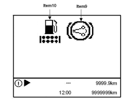
Item 9: Alarm indicator of oil-water separator.
When oil-water separator alarms, the indicator symbol begins to indicate.
Item 10: Working indicator of exhaust valve brake (EVB)
When exhaust valve brake works, the indicator symbol will display on LCD.
6.4.Vehicle Status Adjustment/ Checking the Page
It is used for entering into vehicle status adjustment/ checking page layout, as picture:
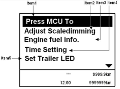
Procedure:
1.Press the menu button and enter (as item 1 of picture 6.5):
2.Brightness adjustment of LCD (as item 2 of picture 6.5)
3.Fuel consumption situation (Refer to item 3 of picture 6.5) (It is only restricted to the vehicle with common rail engine).
4.Time adjustment (Refer to item 4 of picture 6.5)
Brightness Adjustment of LCD
Turn menu knob until the background of Brightness adjustment of LCD turns to yellow, and then press menu button to enter page shown as picture 6.6: Brightness adjustment of LCD (Item 1).
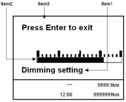
The Brightness and columniation bar (Item 2) will increase or decrease as long as turning menu button to left or right, the brightness reach maximum when the columniation bar is full.
When adjust to the brightness meets requirement, press menu button for one time (Item 3) to quit brightness adjustment. In this case, the interface comes back to the page shown in picture 6.5, and the chosen brightness will be saved in the CBCU.
Before adjusting the brightness of LCD next time, the brightness saved before will be shown on the background.
When the small lamp is lights up, adjust the brightness of LCD, the background brightness of combination instrument and brightness of tilting switch head lamp are adjusted in the same time.
Brightness adjustment mode would be cancelled if any switch of interaxle differential, interwheel differential or all-wheel driving turns off, and the current brightness will be saved in CBCU.
Fuel Consumption Situation (Picture 6.7)
It is used for displaying fuel consumption situation of vehicle with common rail engine only. It will not display this interface if the vehicle is not equiped with common rail engine.
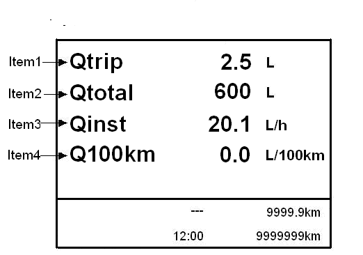
Item 1: Subsection mileage fuel consumption (Qtrip) display:
Press down reset button of subsection mileage /subsection mileage fuel consumption on the combination instrument and keep two seconds, the subsection mileage fuel consumption (Qtrip) will be reset.
Item 2: Engine total fuel consumption (Qtotal) display
Item 3: Hour fuel consumption display (Qinst)
Item 4: Fuel consumption (per 100km) display (Q100km):
When the value of Q100km is beyond 150 L/100 km, cancel display of fuel consumption (1/100km), hour fuel consumption will display only.
Time Adjustment
When system disconnects with VDO tachograph, enter time setting through operating menu knob.
Turn the menu knob to right until the background of time adjustment turns yellow, press down menu knob/switch and enter time adjustment interface .
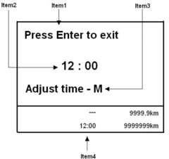
Press down the menu knob one time, enter into hour adjustment, and the hour position is flashing. Turn left to decrease, turn right to increase; the adjustment range is displayed circularly within 0-23.
Press down menu knob one time as soon as the hour meets requirement, it will enter minute adjustment mode which is as same as hour’s. It is circled within 0-59. After adjusting in the right place, save it through pressing down menu knob referring to showing, and exit.
Exit method:The adjustment mode will exit if any switch of interaxle differential, interwheel differential or all-wheel driving turns off in this process, and the current time will be saved in the system.
The time setting interface will not be displayed if the VDO tachograph is installed and connected with CAN bus.
6.5.System Errors Information
The errors information will be displayed on the LCD when the system errors occur, such as sensor connecting error, lower brake air pressure and overtime of CAN communication of engine, ABS (Refer to picture 6.10).
When new error occurs, it will displayed on LCD automatically.
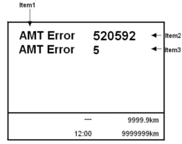
For the system in support of CAN-DMI diagnosis function, the SPN code and FMI code of error information of AMT and ABS systems will be displayed on the interface.
For the error information shown on the LCD, find out error source according to annex A ABS (WABCO) errors code table.
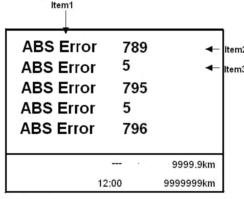
Above picture 6.11 is the interface displaying ABS errors, when ABS errors occur.
Take the case of ABS, above displayed information shows that:
Item 1 ----ABS error: error source is ABS system;
Item 2 ----789: SPN code, error position will be sensor of left front wheel as per Agreement J1939;
Item 3 ---- 5: FMI code, error position will be lower electricity than requirement or open circuit as per Agreement.
Words Displaying Mode (Picture 6.12)
The error information excepting getting by DMI diagnosis of CAN system will be displayed on the interface in the form of words.
All displayig error information will be ranked as per priority level, if many errors happen, the errors with high priority will be displayed firstly such as the errors of brake, body safety and engine safety.
As per the error information shown on the LCD, find out error source and removing methods according to annex B System error information and exit methods.
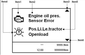
Item 1: The first error symbol;
Item 2: The text description of the first error. And it will be displaying on two rows if the information more than one row.
Item 3: The arrowhead of page up;
Item 4: The second error symbol;
Item 5: The text description of the second error. And it will be displaying on two rows if the information more than one row.
Item 6: The arrowhead of page down;
Item 3 will be displayed on the interface if the error information can not displayed on one page fully and not displayed on the first page as well;
Item 6 will be displayed on the interface if the error information can not displayed on one page fully and not displayed on the last page as well;
Item 3 and Item 6 will be displayed on the interface at one time if the error information displays on many pages and not displayed on the first page or last page;
If error occurred is very serious, the serious error alarm indicator STOP will light up, and the buzzer alarms continuously when engine is working.
Press down menu knob, the buzzer alarm sound will close for a while, but it will restart to alarm one minute later or new serous error happened within one minute later on.
When common error happens, the alarm indicator lights up. Meanwhile, if the following error happens with engine operating, the buzzer alarm ten times in the form of one time per second.
After removing all errors, the buzzer will be silent, and symbols of all error information will disappear.
The alarm interface will return back to normal driving interface.
6.6.System Operation
Sleep mode means that the CBCU is under power saving status, and system does not work.
Operating mode means that CBCU is under working status, the program and all connectors are working.
There are three waken methods, different signal with different waken object, details as following:
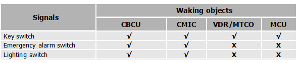
All the system starts to work, the communication connections between them will be established and the vehicle enters driving status if connected with ABS or common rail engine.
Emergency Alarm Switch Wake-up
Under the condition that the key switch close and the emergency alarm switch turn on only, body central computer will be waken up partly and the LCD of instrument does not work, in this case, the emergency alarm, that is, steering lamps light up.
Lighting Switch Wake-up
When the key switch is off and lighting switch is on, function of CBCU will be wakened partly, and the lamps controlled by lighting switch are working such as position lamp, height lamp, side indicator, instrument backlighting and switch indicator.
Turn-on and turn-off voltages of emergency alarm switch wake-up and lighting switch wake-up can be defined by program.
Key switch delays 1 second after closed, the system will return to sleeping status which makes sure all systems exit working status safely.
6.7. System Electrify and Self-checking
When the key switch is at the ON position, that is, bus system will self-check after KL15 turning on. After that, all parts will operate as following:
All instruments: Every instrument finger starts from mechanism terminal, and rotate to scale span within 2 seconds. Later on, the odometer and engine tachometer return to zero position, and air pressure gauge, fuel gauge and water temperature gauge show the real value of current system.
All indicators: All indicators will light up for one second, and then return to real condition.
LCD: Interval of two seconds, it displays CNHTC logo firstly and then displays normal driving interface (displays voltage and oil pressure).
After self-checking, if any switch of interaxle differential, interwheel differential lock switch and all-wheel driving switch is on, the differential lock indicator interface will be displayed;
If above mentioned differential locks are not engaged and error happenes, the interface will enter into error information page;
If the two situations above mentioned do not exist, but the working indicator symbols of other indicator interface is working, the system will switch to indicator interface.
If above mentioned three situations do not appear, the system will stay on normal driving interface.
6.8. System Turn-off
If the system is activated by emergency alarm switch or lighting switch, it will return to sleeping status after switch is off.
Disconnect switch, the system will delay for one second to return to sleeping status.
In this case, all working loads are off, and the instrument fingers go back to zero position, the instrument backlighting will be off.
Otherwise, all components including the system control units, wire harness and electronic components of whole vehicle may be damaged, and system data may be lost and down to cause vehicle unavailable!
6.9. LCD Menu and Interface Operation
Only one menu is displayed on the LCD every time. But the needed content is more than one item, so it is needed to switch between them.
Turn the menu knob to right to browse downwards;
Turn the menu knob to left to browse upwards;
When the displayed differential lock information is more than one screen, press down menu knob to display next information, all information can be displayed in turns.
If the screen is not enough to display needed error information, turn menu knob to right or left to display more information.
After system electrifying and self-checking, interface displays in priority order.
9. Indicators
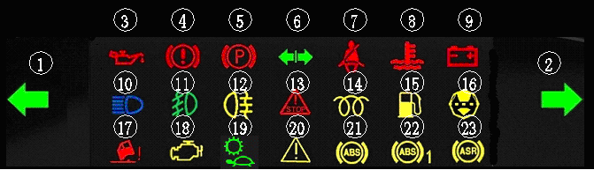
Signal lamp symbol and function:
|
Code |
Description |
Color |
|
1 |
Left steering indicator |
Green |
|
2 |
Right steering indicator |
Green |
|
3 |
Oil pressure alarm indicator |
Red |
|
4 |
Low air pressure alarm indicator |
Red |
|
5 |
Parking brake indicator |
Red |
|
6 |
Trailer steering indicator |
Green |
|
7 |
Safety belt alarm indicator |
Red |
|
8 |
High water temperature alarm indicator |
Red |
|
9 |
Charging indicator |
Red |
|
10 |
High beam indicator |
blue |
|
11 |
Front fog lamp indicator |
Green |
|
12 |
Rear fog lamp indicator |
Yellow |
|
13 |
Serous alarm indicator |
Red |
|
14 |
Preheat working indicator |
Yellow |
|
15 |
Fuel lower level alarm indicator |
Yellow |
|
16 |
Air filter plug alarm indicator |
Yellow |
|
17 |
Cab unlocking alarm indicator |
Red |
|
18 |
Engine error indicator |
Yellow |
|
19 |
Transmission lower gear range indicator |
Green |
|
20 |
Common alarm indicator |
Yellow |
|
21 |
Tractor truck ABS indicator |
Yellow |
|
22 |
Trailer ABS indicator |
Yellow |
|
23 |
ASR indicator |
Yellow |
1. Left steering indicator
2. Right steering indicator
Left-side or right-side steering indicator will flash according to steering signal, the flash frequency of indicator will be around two times than normal situation if one of steering lamp meets errors. All the steering lamps and left/right side indicators will flash when press down alarm indicator switch.
3. Lower oil pressure alarm indicator
This lamp will light up when the engine oil pressure is low. In this case, stop the vehicle and engine, check immediately or contact with local service station to maintain if it is necessary.
4. Lower air pressure alarm indicator
This lamp will light up when the brake air pressure is lower. Contact with local service station to maintain if it is necessary.
5. Parking brake indicator
This lamp will light up when the vehicle stops and turn on the hand brake switch.
6. Trailer steering indicator
The green lamp will light up when turn on trailer steering indicator; this lamp will display with continuouslly flash as long as the lamp meets errors.
7. Safety belt alarm indicator
This lamp will light up with alarm, if driver does not fasten safety belt after starting.
Higher water temperature alarm indicator
This lamp will light up when the water temperature is high, for the time being, stop the vehicle and check water level of engine. Contact with local service station to maintain if it is necessary.
Charging indicator
When the generator works with normal situation, the lamp is off; when the generator meets errors, the lamp will light up.
10. High beam indicator
This lamp will light up when turn on the headlamp switch and distance lamp switch.
11. Front fog lamp indicator
The green lamp will flash when turn on the front fog lamp indicator; this lamp will display with continuouslly flash as long as the lamps meet errors.
12. Rear fog lamp indicator
The yellow lamp will flash when turn on the front fog lamp indicator; this lamp will display with continuouslly flash as long as the lamps meet errors.
13. Serious alarm indicator
This lamp will light up when the vehicle meets serious errors. For the time being, stop vehicle and check, contact with local service station to maintain if it is necessary.
14. Preheating indicator
When turn on starting switch to start the engine, the lamp will light up to preheat the engine; and the lamp will be off after engine starting.
15. Low fuel level alarm indicator
This lamp will light up when the fuel level of fuel tank is low. In this case, supply the fuel to fuel tank.
16. Air filter plug alarm indicator
The lamp will light up when much dust on filter lead to air intake blocked. Clean the filter or change it.
17. Cab unlocking alarm indicator
This lamp will light up when the door unlock. In this case, lock the door again.
18. Engine error indicator
This lamp will light up when engine meets errors. In this case, stop the vehicle and check, contact with the local service station to maintain if it is necessary.
19. Transmission lower speed range indicator
This lamp will light up when the transmission is on lower speed range (1~4 gear).
20. Common alarm indicator
This lamp will light up when the vehicle meets common errors. In this case, stop the vehicle and check, contact with the local service station to maintain if it is necessary.
21. Tractor truck ABS indicator
The ABS system will operate when the tractor truck brakes. This lamp will light up when the ABS system meets errors.
22. Trailer ABS indicator
The ABS system will operate when the trailer brake. This lamp will light up when the ABS system meets errors.
23. ASR indicator
The ASR system will operate when the vehicle slide during starting or accelerating. This lamp will light up when the ABS system meets errors.
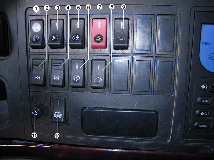
Roller switches and function illumination (Including indicators. It is invalid when the key switch is on 1 gear, unless specified description)
|
Item |
Description |
Status |
Function |
Remarks |
|
|
1 |
Distance Lamp Switch |
0 |
Off |
|
|
|
1 |
On |
|
|||
|
2 |
Interwheel Differential |
0 |
Off |
|
|
|
1 |
On |
Interwheel differential magnetic valve will be driven, and the indicator will be flash until interwheel differential switch put in right place, the indicator light up completely. |
|||
|
3 |
Front Fog Lamp Switch |
0 |
Off |
|
|
|
1 |
On |
Precondition: Shift 1 of lighting switch have been turned on. |
|||
|
4 |
Interaxle Differential |
0 |
Off |
|
|
|
1 |
On |
Interaxle differential magnetic valve will be driven, and the indicator will be flash until interwheel differential switch put in right place when the indicator light up fully. |
|||
|
5 |
Rear Fog Lamp Switch |
0 |
Off |
|
|
|
1 |
On |
Precondition: 1) Shift 1 of lighting switch have been turned on, front fog lamp have been turned on also; or 2) Shift 2 of lighting switch have been turned on. |
|||
|
6 |
Working Lamp Switch |
0 |
Off |
|
|
|
1 |
On |
Working lamp driven |
|||
|
7 |
Serious Alarm Switch |
0 |
Off |
|
|
|
1 |
On |
1,2,3,4 shifts of key switch are available. |
|
||
|
8 |
ECU diagnostic switch |
0 |
Off |
|
|
|
1 |
On |
|
|||
|
9 |
Horn transferring switch |
0 |
Electric horn |
Press horn button on the steering wheel |
|
|
1 |
Air horn |
Press horn button on the steering wheel |
|||
|
10 |
ABS Checking switch |
0 |
|
|
|
|
1 |
|
|
|||
|
11 |
Screen adjustment button |
|
|
|
Global Sales Hotline
Tel: 0086-531-58057777
Fax: 0086-531-58067777
Email: export@sinotruks.cn